|
|
Abdellah Touhafi |
SURReCA |
||||||||||||||||||||
|
Home | Contact | Research Interests | Education | Rec. Computing | Acoustics | Thesis Subjects |Publications |
||||||||||||||||||||||
|
SURReCA |
||||||||||||||||||||||
|
Download
PDF |
SURReCA : a scalable runtime |
reconfigurable computing system | ||||||||||||||||||||
|
SURReCA (Scalable
Uniform Runtime Reconfigurable Computing Architecture)
is a scalable runtime reconfigurable computer that consists of a set of
distributed computing nodes, which can be interconnected in a mesh
structure. The computing nodes can be runtime reconfigured which means
that the structure of their arithmetic and logic unit can be chaned at
runtime. This in order to change the computing structure in respect to
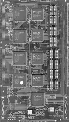
the needs of the application. A prototype system that contains four
computing nodes has been built. See The SURReCA node architecture consists of three parts: a part that contains the computing elements, a part that contains the memory resources and a centrally placed part that implements the reconfiguration engine. The computing layer and the configuration engine have both four communication-links, such that the nodes can be interconnected in a mesh structure. This way, the RTR system can benefit from a large amount of computing resources, with a tightly interconnected reconfiguration engine of which the reconfiguration bandwidth scales linearly with the amount of computing resources. The computing layer contains the computing resources, the local data memory and two buffer controllers. One controller keeps track of the output buffer state and one controller is used to check the state of the input buffer. The input buffer is to be interpreted as a source buffer of a context and the output buffer implements a sink buffer in which data values are stored. |
Figure 1: SURReCA prototype
|
|||||||||||||||||||||
|
Control |
Layer |
|||||||||||||||||||||
|
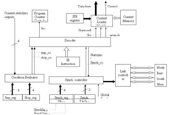
The control layer contains the configuration engine that is the base of the distributed controller. Important is that the configuration engine is implemented as a programmable unit that uses the structure information elements together with some instructions to control the computing layer and to synchronize the distributed system. All the information elements of the contexts are grouped into a fixed record structure and are located in the contexts memory. The SURReCA node contains also an instructions memory that is used to specify the reconfiguration function. For clarity a separated bus for the instruction memory, the context memory and the application data memory is drew. In practical realization the busses are shared because of reasons explained in the previous chapter. Multi-node SURReCA systems can be built by interconnecting the communication links of the nodes in a mesh structure or another convenient structure. |
||||||||||||||||||||||
|
|
||||||||||||||||||||||
|
Instruction |
set | |||||||||||||||||||||
|
|
The DCC
computing model represents a computing problem by a reconfiguration
graph and a structures graph. In that optic, the handling of the
reconfiguration graph is associated with the reconfiguration controller.
The reconfiguration controller implements the reconfiguration function
and the state transition function of the DCC model’s reconfiguration
manager. For the specification of the state transition function and the
reconfiguration function, an instruction set is defined. An application
is hence specified as a program containing instructions, instruction
parameters, context pointers and pointers to buffers.The controller
determines what actions must be taken to change a structure by means of
the instructions. For the implementation of a complete DCC specified
application, only three instructions are needed to control the whole
distributed system. -JMP
-SYNCH
The instruction has also two parameters, the first parameter specifies a pointer to a record that contains all the information about the structure that must be activated and the second parameter specifies the deactivation condition. The idea is that once a structure is activated it will be kept active until the specified stop_condition is met. In case the next instruction is also a move instruction, the handling of that instruction will be blocked until the active context is deactivated. In case the next instruction is a SYNCH instruction, that instruction will be handled during the configuration phase. In such a case the SYNCH-instruction acts as a start condition for the configured context. The stop condition is defined as four two bit values, where each value is associated with a context switcher output. The values in the register test for the following context switcher output:
|
|||||||||||||||||||||
|
The information of the structural setup is stored in
a structure information record (SIR) to which the SIR-register points
The organization of the record is as shown here. |
|
|||||||||||||||||||||
|
|
||||||||||||||||||||||
|
|
||||||||||||||||||||||