|
|
Abdellah Touhafi |
ATM Simulation on RC Systems |
|
|
Home | Contact | Research Interests | Education | Rec. Computing | Acoustics | Thesis Subjects |Publications |
|||
|
What is? |
|||
|
ATM ATM switch DCC model
|
Methodology |
||
|
Queuing models are often used to study the behavior and performance of complex computer- and data networks. In such models, a system is represented by a set of queues, servers and routing elements. The derived queuing model is analyzed in order to determine the performance of the physical system for a given stimulus. Given a queuing network, we can consider the use of simulation techniques as well as the use of mathematical analysis techniques for its study. The complexity of the pure mathematical approach makes that simulation of queuing networks is put in favor for the study of large queuing systems. |
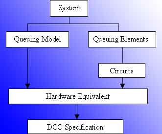
Fig. 1: Implementation steps |
||
 |
|||
|
For the simulation we can often rely on existing simulation algorithms and general purpose computing systems. An important limiting factor in this approach is the computing time. Due to the raising bandwidth of modern computer- and data-networks on one hand and the increasing network-size on the other hand, the required computing time often becomes unworkable. Reconfigurable computing techniques might offer a solution to this limitation up to a certain level. To demonstrate the usefulness of scalable RTR systems for simulation purposes, an ATM switch fabric simulator is implemented on the SURReCA system. The implementation of the simulator goes in four steps. First, the physical system is translated into its queuing model. That queuing model is then translated to a convenient simulation circuit. The simulation circuit is further specified in its DCC computing-model equivalent. The derived DCC specification can then be implemented and run on the SURReCA system.A crucial step in the design flow is the construction of circuits for the hardware equivalent. The latter contains the circuit descriptions of the queuing elements and how they are related in order to form the whole system queuing model. In order to generate the circuit descriptions and their compiled bit-representation (i.e. partial context), several tools were used for the experiments that are described later on. An overview of the used tools and a simplified design flow are shown in Fig.2 . The first step in the design flow is to describe the behavior of the queuing-model elements using a convenient design entry tool. That description is then translated into a netlist, which can be used by the placement and routing tool. The placement and routing tool generates a bit-stream, which is used to program the XC6200 DPGA. The correctness of the generated circuit can be verified using an emulation board and software that helps to monitor the emulation board. The experiments that have been conducted used schematic entry as well as HDL description to specify the behavior of the components. |
|||
|
Fig 2: Design flow |
For schematic entry the Viewlogic design environment is used. For HDL entry, LOLA [122] and structural HDL descriptions were tried out. The LOLA language is then compiled in the Trianus system [110]. The latter is an integrated netlist generator and placement and routing system. The Trianus system however turned out to be not stable enough and the LOLA language is to restrictive. In stead, Xilinx Velab compiler [123] is used to generate a netlist out of structural HDL. The Xilinx Xact Step 6000 tool is then used for the placement and routing of the generated netlist. A great advantage of the Xact step tool is that it provides an easy way to improve the placement manually. The placed and routed design is then translated into a .cal file which is the bitstream representation of the ciruit. For the verification of the correctness of the circuits, an emulation board is used in combination with WebScope [124]. |
||
 |
|||
|
|
|||
|
|
|||
|
|
|||