Parallelisation & Intelligence
Ontologies for model reuse.
6/3/2002
Abstract
In simulation we build models of the world. In the keynote speech of the
European Simulation Multiconference 2001 [Meersman 2001, Vangheluwe 2001]
the need for reuse of models is expressed. Ontologies promise an
adequate technology for this:
-
[Swartout 1999] "set of concepts and terms", "share a common terminology",
-
[Chrandasekaran 1999] "Given a domain, its ontology forms the heart of
any system of knowledge represenation for that domain"
-
[Gomez-Perez 1999] "ontologies can be used to communicate between systems"
-
[van der Vet 1998] "the ontology supports unambiguous definitions of concepts
..." "the ontology suppies the meaning..."
This project will investigate the benefits of introducing ontologies in
the field of discrete event simulation (DES), as developed at the PADX
lab (parallel.vub.ac.be), in cooperation
with StarLab (starlab.vub.ac.be).
Discrete Event Simulation (DES)
Discrete Event Simulation keywords: processes, behaviour, events, topology,
simulation algorithm [see website for an introduction to DES: http://parallel.vub.ac.be/research/pads/]
The DES environment of the PADX lab is written in C++.
Models developed: street [Aerts], telecommunication network, telecommunication
component [Geudens: Router], internet [Wang], logical circuits [Maman],
fpga's [Bousis].
An ontology can be developed for the 5 main parts of DES:
-
Simulation Terminology
-
Events
-
Processes
-
Process behaviour
-
Topology
-
The modeling process
Reuse of simulation algorithms is another challenge, but I think it goes
beyond the scope of ontologies...
Reuse
-
reuse within our DES environment
-
reuse with other environments
-
"bereikbaarheid of things"
-
clear, standard terminology
-
implementation-indepence through code generation
-
recognition and similarity detection
The ontology approach
-
list of concepts (terminology)
-
relationships between them
-
with ORM (Object Role Modeling)
-
taxonomy/hierarchy
-
implementation-independent description, for example with XML
-
expressing behaviour... & translation into code
More ontology things (but their use is not clear to me)
-
Conceptual graphs [Sowa], KIF [...], XML [...]
-
recognition/ similarity detection of concepts
[Gruber 1993] "Ontological commitments are agreements..."
Benefits of using ontologies...
-
clear terminology (standardisation): clear choice of names, subtype,
etc with their relationships => with ORM
-
taxonomy: hierarchy of events & processes, leading to structured approach
of the models.
-
close to natural language
-
'verhoogt bereikbaarheid'
-
reuse
-
reuse of topologies, with an implementation-independent description
-
=> use of XML etc in our simulator??
-
description by an ontology can be used to automatically generate implementations
-
create templates for rules that can generate code
More possible benefits, but less clear:
-
reasoning on description
-
recognition of concepts (similarity detection)
-
characteristic detection
cooperation with other research labs?? this to test the reuse & exchange
of models
experiments on ontologies in a realistic environment
Applying the ontology approach
1. Simulation terminology
=> ORM, see Appendix 1
=> terminology will be used in implementation!!
-
definition of DES
-
what systems can be simulated with DES?
check different formalisms, in other research labs
2. Events
-
Event subtypes add specific information (properties) => events classification
(using multiple inheritance) with clear terminology for the properties
and their types. See Appendix 2
-
this can generate automatically the C++ code
-
the meaning of the event properties
are entirely defined by the processing behaviour,
-
eg:
-
the size of an event determines its delay in a process
-
the destination of an event determines it outputchannel
-
the source of an event is determined by the process that created it
-
can this be described formally?? It could be recognised and tested!?
3. Process Classification
-
Define commonly used processes: delay, queue, mux, demux, router, source,
sink, ...
-
=> Classification according to their configuration and behaviour
-
See Appendix 3 for a classification of demultiplexer
subtypes.
-
Classification according to their #inputs, #outputs and type of channels
(= type of incoming events)
-
Classification of Logical processes: AND, OR, NOT, FLIPFLOP, combinations
of these, ...
4. Process behaviour
See Appendix 4 for the behaviour description
of the demux processes.
the ultimate goal of reuse is the possibility to write the behaviour
of processes in a 'language' that can be 'understood' by any simulation
environment:
-
a description language (templates for rules)
-
code generation in the formalism of the simulation environment
-
automatic classification of models
-
similarity detection: recognise equal or similar processes (eg developed
by different research teams)
-
could be used for reasoning about processes
5. Topology description
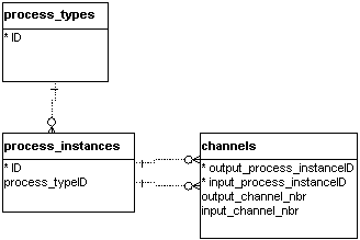
The topology of a model consists of processes that are connected by channels.
Each process is an instance of a certain process type (eg mux, demux, ...).
-
formalism independent description: by use of XML??
-
see Appendix 5a for a full description of process
instances and their connections
-
but typically, topologies have size parameters, like the number of inputs
of a router (see an example in appendix 5b)
-
Use the description for model recognition: recognise similarities and difference
of models by their topology.
-
It is usefull to recognise that different topologies only differ in their
topology parameters.
-
Also for symmetry recognition in topologies (see Project),
ontologies could be helpfull.
-
A superprocess is an aggregation of basic processes (see appendix
5c).
6. The modeling process
When modeling a new system, the modeler creates new event types and new
processes. The approriate ontology-way of doing this, is by integrating
it in the existing ontology-database:
-
defining the new concepts from the natural language model description.
-
subtyping events by creating new event properties, add them in the hierarchy
-
with the meaning-description of an event property, this classification
could be automated...
-
adding new processes in the process hierarchy
=> define the standard approach for the modeling process.
MORE:
Starlabs interpretation layer could here be seen as the model of the
system .. [dixit Mustafa Jarrar].
References
-
see lab thesis's on models
-
Starlab formalism
-
[Meersman 2001] Meersman New Frontiers in Modeling Technology: The Promise
of Ontologies
-
[Vangheluwe 2001] reuse between different formalisms
-
more available on the lab
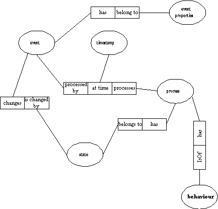
Appendix 1: ORM of DES concepts
Appendix 2: Event classification
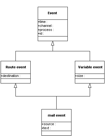
When creating the event classification tree, we see that we have
basic subtypes describing the basic properties of events. Events will
(multiple) inherit from these.
Appendix 3: Demultiplexer ("demux")
taxonomy
A demultiplexer is a process with one input and N outputs of the same type,
it is the opposite process of a multiplexer where N inputs go to 1 output.
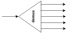
The behaviour of a demux should tell what happens with an incoming event.
There a an infinite number of possibilities, here are some of the most
commonly used:
-
broadcast: the event is sent to each output.
-
routing: the event has information on where should be sent to (destination
process). The demux has a routing table (mapping destination => outputchannel)
for the routing.
-
random output: the event is sent to a randomly chosen output. A
subtype of this is the use of a probability distribution.
-
alternating output: each incoming event is sent to the next output
channel.
We can build a classification tree (taxonomy) for this:
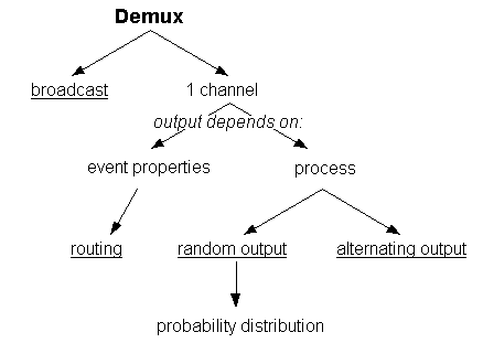
Appendix 4: Demux Process Behaviour
| subtype of demultiplexer |
configuration |
state |
behaviour |
| broadcast |
- nbr-of-outputchannels
- delay |
none |
when an event enters
add delay to event.timestamp
event.outputchannel = 0
for i = 1 to (nbr-of-outputchannels - 1)
new_event = copy(event)
new_event.outputchannel = i |
routing
only accepts route-events |
- nbr-of-outputchannels
- delay
- routing table: mapping of all destinations to the corresponding
outputchannel |
none |
when an route-event enters
add delay to route-event.timestamp
lookup the corresponding outputchannel for route-event.destination
-> set route-event.outputchannel |
| random output |
- nbr-of-outputchannels
- delay |
none |
when an event enters
add delay to event.timestamp
event.outputchannel = random between 0 and (nbr-of-outputchannels
- 1) |
| alternating output |
- nbr-of-outputchannels
- delay |
- last- outputchannel |
when an event enters
add delay to event.timestamp
add 1 to last-outputchannel
if last-outputchannel=nbr-of-outputchannels then
last-outputchannel = 0
event.outputchannel = last-outputchannel |
Appendix 5a: Topology description
When creating a topology, we instantiate processes and connect them by
channels. Each process can have several channel inputs and/or outputs,
so we number them. The Entity-Relationship Diagram of the topology looks
like this:
Appendix 5b: Parametrized topology
Topologies of a model can be parametrized, as in the following example,
where the outputs of the demux and the number of sinks is a parameter (n):
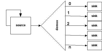 The topology description will look like this:
get topology parameter n
create source
connect source outputchannel to source inputchannel
create demux
connect source to demux
for i = 0 to n
create sink
connect demux outputchannel
i to sink
end for
Is such a parametrized description possible in XML?
Appendix 5c: Superprocesses
The client superprocess consists of a source, which sends events, and a
sink, which receives the answers:
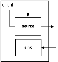 Once created, a superprocess can be used like any other process.


